Mass-flow shares, not thrust shares. Same schematic geometry; illustrative speeds.
A SIMPLIFIED TEACHING MODEL
EXHIBIT 05 / 4 min OF CURIOSITY
The jet engine.
How does moving air move an airplane?
A river of air. A fire inside. A way to fly.
6 SHORT CHAPTERSFREE & OPEN SOURCE
01 / 06
FOLLOW THE AIR
Push air back. Move forward.
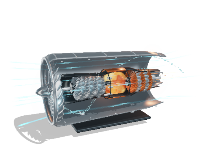
An engine accelerates air toward the rear. The reaction supplies a forward force on the airplane. The large front fan moves a great deal of that air.
Thrust comes from changing the momentum of the air. A visible flame is not required at the exhaust.
TRY IT YOURSELF
Select the fan, then rotate to its front. Follow the cyan air entering the engine.
Go deeper +
This teaching model shows flow direction and linked shafts, not a prediction of force. A real thrust calculation also needs mass flow, velocities and pressure terms.
Fuel burns in the combustion chamber. The heated gas continues toward the turbines. During steady running, combustion is continuous.
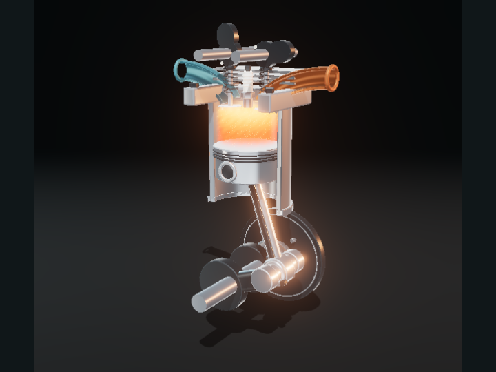
The hot gas carries energy that the turbines can extract. The flame is held in the combustor rather than pulsing like a piston engine.
TRY IT YOURSELF
Pause at two different angles. The combustor stays lit: there is no repeating spark-plug stroke.
Go deeper +
Fuel injectors, cooling passages and flame stabilization are represented only schematically. No startup sequence, temperature or combustion chemistry is simulated.
The rest of the fan’s airflow travels around the core through the bypass duct. It does not pass through the combustion chamber. Both streams contribute to the engine’s thrust.
Bypass ratio compares the mass flow around the core with the mass flow through it. It is not the ratio of their thrust contributions.
TRY IT YOURSELF
Compare 2:1, 5:1 and 10:1. Read the two mass-flow shares and trace the larger stream around the core.
Go deeper +
For bypass ratio B, core share is 1/(1+B), and bypass share is B/(1+B). These are ideal flow comparisons in one schematic geometry, not three calibrated engine designs.
Schematic overview. The explanation and equations remain available without JavaScript or 3D.
CHAPTER 1
Push air back. Move forward.
An engine accelerates air toward the rear. The reaction supplies a forward force on the airplane. The large front fan moves a great deal of that air.
Thrust comes from changing the momentum of the air. A visible flame is not required at the exhaust.
This teaching model shows flow direction and linked shafts, not a prediction of force. A real thrust calculation also needs mass flow, velocities and pressure terms.
CHAPTER 2
A smaller stream takes the inside route.
Some air enters the core. Alternating rows of rotating compressor blades and fixed stator vanes prepare it for combustion.
The compressor raises pressure. Stators redirect the flow between rotor rows; they do not spin with the shaft.
The number and shape of the compressor stages are simplified. The flow traces do not calculate pressure, density, or individual blade aerodynamics.
CHAPTER 3
A contained, continuous fire.
Fuel burns in the combustion chamber. The heated gas continues toward the turbines. During steady running, combustion is continuous.
The hot gas carries energy that the turbines can extract. The flame is held in the combustor rather than pulsing like a piston engine.
Fuel injectors, cooling passages and flame stabilization are represented only schematically. No startup sequence, temperature or combustion chemistry is simulated.
CHAPTER 4
The exhaust does work on its way out.
Hot gas turns turbine blades before leaving the core nozzle. The turbines draw energy from that stream to drive machinery farther forward.
A turbine and a compressor do different jobs: one extracts shaft work from the gas, while the other supplies work to it.
Blade profiles and rotor speeds are illustrative. The scene does not solve the thermodynamic cycle or predict how much work each stage extracts.
CHAPTER 5
Two shafts, one inside the other.
One shaft links the high-pressure turbine to the core compressor. Another passes through it, linking the low-pressure turbine and the fan.
The two spools can turn at different speeds. Each shaft keeps its own connected parts synchronized.
This is an unbranded two-spool layout. The illustrated 2:1 spool-speed ratio is chosen for legibility; it is not a real engine specification.
CHAPTER 6
Most of this air misses the fire.
The rest of the fan’s airflow travels around the core through the bypass duct. It does not pass through the combustion chamber. Both streams contribute to the engine’s thrust.
Bypass ratio compares the mass flow around the core with the mass flow through it. It is not the ratio of their thrust contributions.
For bypass ratio B, core share is 1/(1+B), and bypass share is B/(1+B). These are ideal flow comparisons in one schematic geometry, not three calibrated engine designs.
Sources, credits & model boundaries+
What this model explains
Schematic two-spool turbofan with illustrative blade profiles, 2:1 spool speeds and qualitative flow traces. Bypass presets change mass-flow shares in the same geometry; they do not predict thrust shares, fuel efficiency, temperature, pressure or actual operating speeds. No afterburner or startup simulation.
Original Blender assembly, flow paths and educational prose by OpenEngineering contributors, CC BY 4.0. Editable sources and scripts/build-exhibit-models.py included. No manufacturer CAD.
Code: MIT. Original educational content and assets: CC BY 4.0. No independent mechanical reviewer is credited yet.