(1.00 + 1.00) ÷ 2 = 1.00 · average speed stays the same
A SIMPLIFIED TEACHING MODEL
EXHIBIT 03 / 3 min OF CURIOSITY
The differential.
How can two wheels share an engine but turn at different speeds?
One engine. Two wheels. A clever way to let them disagree.
4 SHORT CHAPTERSFREE & OPEN SOURCE
01 / 04
A CORNER CREATES A PROBLEM
The outside wheel goes farther.
Around a corner, the outside wheel follows a larger circle. If both wheels were forced to turn at the same speed, at least one would have to slip.
We need a shared drive that lets the wheels turn at different speeds. An open differential provides that extra freedom.
TRY IT YOURSELF
Choose a left turn. The right wheel takes the longer path and speeds up; the left wheel slows down.
Go deeper +
For rolling wheels of equal radius, speed is proportional to path radius. With track width w and axle-centre turn radius R, normalized speeds are 1 − w/(2R) and 1 + w/(2R). This model uses w = 1.6 m.
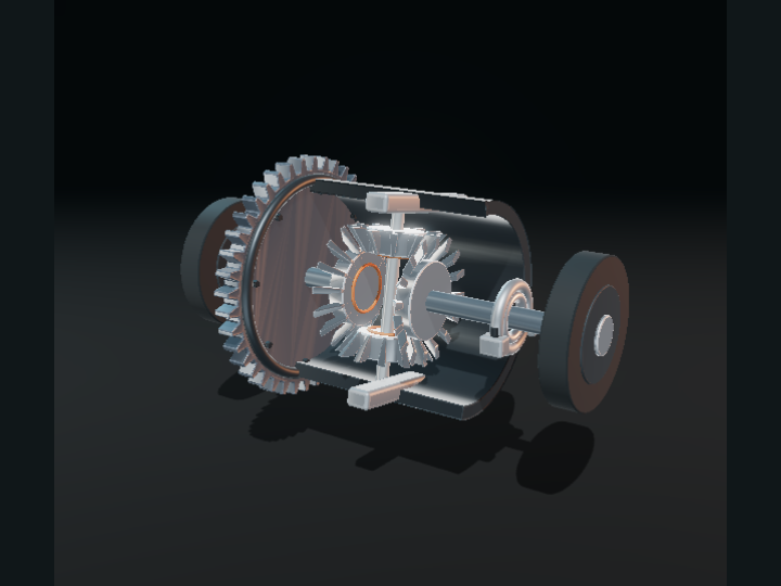
The ring gear turns a carrier. Two small spider gears ride in that carrier, meshing with a side gear connected to each wheel.
Going straight, both side gears turn with the carrier. The spiders orbit the axle without spinning relative to their cross-shaft.
TRY IT YOURSELF
Select straight ahead. Look at the colored markers on both outputs: they keep pace with one another.
Go deeper +
The housing is opened up and the drive pinion is omitted. Side and spider teeth are schematic bevel shapes, not a manufacturing model. Ring gear speed is our prescribed input.
In a turn, the spiders also spin on their own axes. That spin subtracts motion from one side and adds the same amount to the other.
The average output speed always matches the carrier: (left + right) ÷ 2 = carrier. A differential permits the difference; the paths of the wheels demand it.
TRY IT YOURSELF
Turn left, then tighten the radius. Watch the spider motion and the growing difference between the output speeds.
Go deeper +
The turn controls prescribe wheel paths under ideal rolling constraints. The differential does not choose which side needs speed. Torque, road forces, friction and wheel slip are not calculated.
Imagine the differential on a workbench. Keep the carrier turning, but hold the left output still. The right output must turn twice as fast as the carrier.
The mean-speed rule still holds: (0 + 2) ÷ 2 = 1. This is a useful way to see what the gears allow.
TRY IT YOURSELF
Hold the left output, then release it. Compare the speed labels and inspect the spider gears in the exploded view.
Go deeper +
This is a kinematic bench experiment, not a prediction about traction. A real open differential generally supplies equal torque to both side gears; limited grip can constrain the useful drive torque.
Schematic overview. The explanation and equations remain available without JavaScript or 3D.
CHAPTER 1
The outside wheel goes farther.
Around a corner, the outside wheel follows a larger circle. If both wheels were forced to turn at the same speed, at least one would have to slip.
We need a shared drive that lets the wheels turn at different speeds. An open differential provides that extra freedom.
For rolling wheels of equal radius, speed is proportional to path radius. With track width w and axle-centre turn radius R, normalized speeds are 1 − w/(2R) and 1 + w/(2R). This model uses w = 1.6 m.
CHAPTER 2
Straight ahead, share the motion.
The ring gear turns a carrier. Two small spider gears ride in that carrier, meshing with a side gear connected to each wheel.
Going straight, both side gears turn with the carrier. The spiders orbit the axle without spinning relative to their cross-shaft.
The housing is opened up and the drive pinion is omitted. Side and spider teeth are schematic bevel shapes, not a manufacturing model. Ring gear speed is our prescribed input.
CHAPTER 3
The small gears make the difference.
In a turn, the spiders also spin on their own axes. That spin subtracts motion from one side and adds the same amount to the other.
The average output speed always matches the carrier: (left + right) ÷ 2 = carrier. A differential permits the difference; the paths of the wheels demand it.
The turn controls prescribe wheel paths under ideal rolling constraints. The differential does not choose which side needs speed. Torque, road forces, friction and wheel slip are not calculated.
CHAPTER 4
Hold one. The other doubles.
Imagine the differential on a workbench. Keep the carrier turning, but hold the left output still. The right output must turn twice as fast as the carrier.
The mean-speed rule still holds: (0 + 2) ÷ 2 = 1. This is a useful way to see what the gears allow.
This is a kinematic bench experiment, not a prediction about traction. A real open differential generally supplies equal torque to both side gears; limited grip can constrain the useful drive torque.
Sources, credits & model boundaries+
What this model explains
An ideal open differential with equal side gears. Turn radius prescribes the output rates; forces, torque, traction and tire slip are not solved. Bevel teeth and ring drive are schematic. The housing and input pinion are omitted.