A little fire. A lot of ingenuity. Let’s see what makes it turn.
7 SHORT CHAPTERSFREE & OPEN SOURCE
01 / 07
THE BIG IDEA
How does fire become motion?
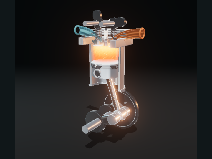
Burning fuel heats the gas inside an engine. The gas expands and pushes on the silver piston. That push is the start of a journey from heat to motion.
Follow the crankshaft: the engine has found a way to turn a straight push into a circle.
TRY IT YOURSELF
Pause, then drag the cycle slider through the orange power stroke. Watch the space above the piston grow.
Go deeper +
Combustion raises the temperature and pressure of the gas. Pressure acts on the piston face. Gas flow, spark and flame are illustrative visual cues tied to the cycle, not calculated pressure, temperature or fluid fields.
An uncontained burst spreads in every direction. A cylinder holds the gas around a sliding piston, directing its useful push along one path.
The piston must move while its rings help seal the gap around its edge. Now we have useful motion, but only in a straight line.
TRY IT YOURSELF
Take the assembly apart. Find the piston rings, then put it back together and scrub the piston between its two extremes.
Go deeper +
This is a cutaway of a simplified cylinder. Real piston rings also manage oil and transfer heat. Gaps, lubrication, friction and thermal expansion are omitted.
Add a connecting rod. Its top end follows the piston up and down; its bottom end follows an offset pin around the crankshaft.
The rod leans as the crank turns, so both ends can follow their own paths without changing its length.
TRY IT YOURSELF
Pause at 90°, then scrub backward to 0°. The rod tilts, but the distance between its pins stays the same.
Go deeper +
With crank radius r, rod length l and crank angle θ, piston position is r cos θ + √(l² − r² sin² θ). This is a kinematic relationship, not a force or torque calculation.
First, draw in fresh mixture. Next, squeeze it. Ignite it for the power stroke, then push the spent gas out. The piston travels down, up, down, up.
Only one of these four strokes supplies combustion power. A complete cycle takes two turns of the crankshaft: 720°.
TRY IT YOURSELF
Tap each stroke below the model. Notice which valve opens and whether the piston is rising or falling.
Go deeper +
We show an idealized spark-ignition four-stroke cycle. Ignition starts at 360°. Real engines typically ignite earlier, and their valve events overlap stroke boundaries.
The valve below the blue passage opens for fresh mixture. The valve below the copper passage opens for spent gas. Both stay closed during compression and most of the power stroke.
The camshaft coordinates these events. It turns at half the crankshaft’s speed, bringing each valve event around once per 720° cycle.
TRY IT YOURSELF
Use slow playback. Follow the camshaft’s white marker while the crank completes two full turns.
Go deeper +
Cam lobes and lift are schematic. Lift follows a smooth sine during the relevant stroke; no rocker linkage, timing belt, realistic cam profile or valve overlap is simulated.
An engine still needs to move between its power strokes. A flywheel stores energy as it speeds up, then returns some as it slows down.
Rotational inertia helps the crank pass through the other strokes. A real engine’s speed fluctuates; the animation stays at the playback speed you choose.
TRY IT YOURSELF
Select the flywheel, then rotate to the rear view. Find the heavy disk connected to the crankshaft.
Go deeper +
Rotational kinetic energy is ½Iω². A heavier rim increases moment of inertia I. This exhibit does not solve dynamics, so removing a visual part would not realistically stop or accelerate the model.
Connect four cylinders to one crankshaft and stagger their cycles. As one finishes a power stroke, another starts. The individual pushes are spread more evenly.
This example uses firing order 1–3–4–2, with a power stroke beginning every 180°. One piston alone supplies a power stroke only once every 720°.
TRY IT YOURSELF
Switch between one and four cylinders. The colored strips show which cylinder is on its power stroke at this instant.
Go deeper +
Four cylinders do not guarantee constant torque or perfect balance. We show phase relationships and geometry, not combustion pressure, vibration or measured power.
Schematic overview. The explanation and equations remain available without JavaScript or 3D.
CHAPTER 1
How does fire become motion?
Burning fuel heats the gas inside an engine. The gas expands and pushes on the silver piston. That push is the start of a journey from heat to motion.
Follow the crankshaft: the engine has found a way to turn a straight push into a circle.
Combustion raises the temperature and pressure of the gas. Pressure acts on the piston face. Gas flow, spark and flame are illustrative visual cues tied to the cycle, not calculated pressure, temperature or fluid fields.
CHAPTER 2
A push needs somewhere to go.
An uncontained burst spreads in every direction. A cylinder holds the gas around a sliding piston, directing its useful push along one path.
The piston must move while its rings help seal the gap around its edge. Now we have useful motion, but only in a straight line.
This is a cutaway of a simplified cylinder. Real piston rings also manage oil and transfer heat. Gaps, lubrication, friction and thermal expansion are omitted.
CHAPTER 3
Turn a line into a circle.
Add a connecting rod. Its top end follows the piston up and down; its bottom end follows an offset pin around the crankshaft.
The rod leans as the crank turns, so both ends can follow their own paths without changing its length.
With crank radius r, rod length l and crank angle θ, piston position is r cos θ + √(l² − r² sin² θ). This is a kinematic relationship, not a force or torque calculation.
CHAPTER 4
One useful push. Four strokes.
First, draw in fresh mixture. Next, squeeze it. Ignite it for the power stroke, then push the spent gas out. The piston travels down, up, down, up.
Only one of these four strokes supplies combustion power. A complete cycle takes two turns of the crankshaft: 720°.
We show an idealized spark-ignition four-stroke cycle. Ignition starts at 360°. Real engines typically ignite earlier, and their valve events overlap stroke boundaries.
CHAPTER 5
The valves need a clock.
The valve below the blue passage opens for fresh mixture. The valve below the copper passage opens for spent gas. Both stay closed during compression and most of the power stroke.
The camshaft coordinates these events. It turns at half the crankshaft’s speed, bringing each valve event around once per 720° cycle.
Cam lobes and lift are schematic. Lift follows a smooth sine during the relevant stroke; no rocker linkage, timing belt, realistic cam profile or valve overlap is simulated.
CHAPTER 6
Keep some motion in reserve.
An engine still needs to move between its power strokes. A flywheel stores energy as it speeds up, then returns some as it slows down.
Rotational inertia helps the crank pass through the other strokes. A real engine’s speed fluctuates; the animation stays at the playback speed you choose.
Rotational kinetic energy is ½Iω². A heavier rim increases moment of inertia I. This exhibit does not solve dynamics, so removing a visual part would not realistically stop or accelerate the model.
CHAPTER 7
More cylinders. Fewer gaps.
Connect four cylinders to one crankshaft and stagger their cycles. As one finishes a power stroke, another starts. The individual pushes are spread more evenly.
This example uses firing order 1–3–4–2, with a power stroke beginning every 180°. One piston alone supplies a power stroke only once every 720°.
Four cylinders do not guarantee constant torque or perfect balance. We show phase relationships and geometry, not combustion pressure, vibration or measured power.
Sources, credits & model boundaries+
What this model explains
A simplified spark-ignition teaching model. Motion and valve timing are prescribed; no combustion, pressure, friction, torque, efficiency or flywheel dynamics are calculated. Front walls are deliberately removed. Cam geometry is schematic.
An influence on explanatory clarity; all text and geometry here are original.
Made in the open
Original Blender geometry, procedural effects and educational text by OpenEngineering contributors. Editable models and export scripts are included; no third-party model assets.
Code: MIT. Original educational content and assets: CC BY 4.0. No independent mechanical reviewer is credited yet.