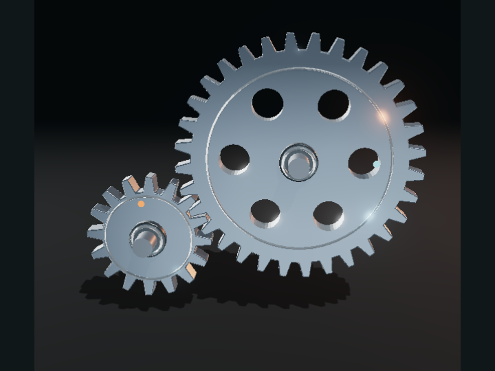
Output rotates in the opposite direction. Losses ignored.
A SIMPLIFIED TEACHING MODEL
EXHIBIT 02 / 2 min OF CURIOSITY
Gear ratios.
How can gears make something stronger but slower?
A little slower. A lot stronger. There’s a trade hiding in these teeth.
4 SHORT CHAPTERSFREE & OPEN SOURCE
01 / 04
PASS THE MOTION
One tooth pushes the next.
Turn the gear with the orange marker. Where the teeth meet, it pushes the output gear the other way. Two external gears always rotate in opposite directions.
The teeth keep their motions linked. At the contact, both gears must move the same distance along their pitch circles.
TRY IT YOURSELF
Pause and scrub backward. Both gears reverse, but they still turn in opposite directions.
Go deeper +
These are ideal external spur gears. The displayed tooth outlines are schematic, not manufacturing-ready involute profiles. Pitch radii grow in proportion to tooth count.
At the same contact force, a bigger output gear has a longer lever arm. It delivers more turning effect—torque—while rotating more slowly.
In an ideal gear pair, power stays the same. Doubling torque halves speed. Real gears lose some energy to friction and other effects.
TRY IT YOURSELF
Switch from 16 → 32 to 16 → 48. Compare the ideal torque and speed ratios below the model.
Go deeper +
Torque ratio = driven teeth / driver teeth when losses are ignored. Power = torque × angular speed. The ratios are calculated; neither an applied load nor real torque in newton-metres is simulated.
Make the driver larger than the output. Now one input turn pushes enough teeth to spin the output more than once.
Gearboxes let a machine choose a useful compromise between speed and turning force. There is no free gain in both.
TRY IT YOURSELF
Choose 32 → 16. Can you predict the speed ratio before looking? Then try another pair.
Go deeper +
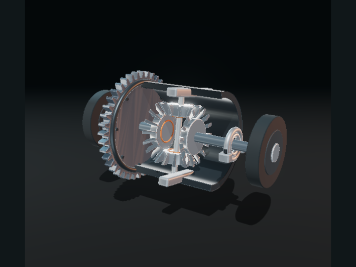
A compound gearbox can multiply several ratios, and an idler can change direction without changing the overall magnitude for a simple chain. Those systems are beyond this two-gear exhibit.
Schematic overview. The explanation and equations remain available without JavaScript or 3D.
CHAPTER 1
One tooth pushes the next.
Turn the gear with the orange marker. Where the teeth meet, it pushes the output gear the other way. Two external gears always rotate in opposite directions.
The teeth keep their motions linked. At the contact, both gears must move the same distance along their pitch circles.
These are ideal external spur gears. The displayed tooth outlines are schematic, not manufacturing-ready involute profiles. Pitch radii grow in proportion to tooth count.
CHAPTER 2
Twice the teeth. Half the turns.
Give the output 32 teeth and the input 16. The input must turn twice to move all 32 teeth of the output past the contact.
The bigger output turns more slowly. The same input motion is spread over more teeth.
Output angular speed / input angular speed = −driver teeth / driven teeth. The minus sign indicates opposite direction. The colored markers help you compare rotation.
CHAPTER 3
Slower can mean stronger.
At the same contact force, a bigger output gear has a longer lever arm. It delivers more turning effect—torque—while rotating more slowly.
In an ideal gear pair, power stays the same. Doubling torque halves speed. Real gears lose some energy to friction and other effects.
Torque ratio = driven teeth / driver teeth when losses are ignored. Power = torque × angular speed. The ratios are calculated; neither an applied load nor real torque in newton-metres is simulated.
CHAPTER 4
Want speed? Give up torque.
Make the driver larger than the output. Now one input turn pushes enough teeth to spin the output more than once.
Gearboxes let a machine choose a useful compromise between speed and turning force. There is no free gain in both.
A compound gearbox can multiply several ratios, and an idler can change direction without changing the overall magnitude for a simple chain. Those systems are beyond this two-gear exhibit.
Sources, credits & model boundaries+
What this model explains
Ideal external gears with schematic teeth and no backlash, friction, material deformation or load. Torque is an ideal ratio, not a simulated force.